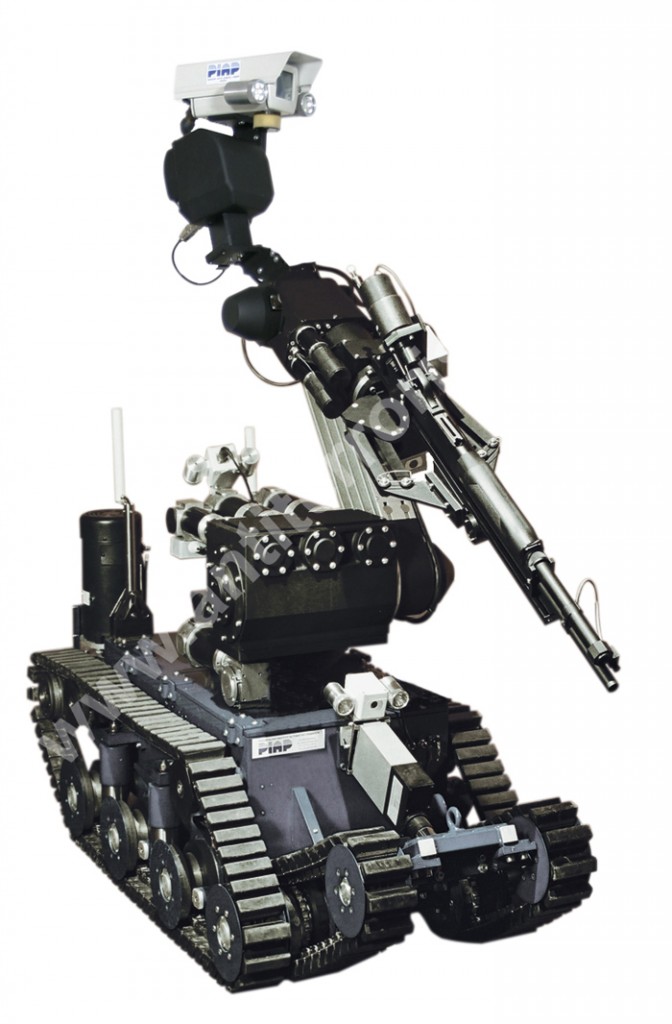
Inspector G2 - Demining Robot
تثبيت التطبيق
How to install the app on iOS
Follow along with the video below to see how to install our site as a web app on your home screen.
ملاحظة: This feature may not be available in some browsers.
أنت تستخدم أحد المتصفحات القديمة. قد لا يتم عرض هذا الموقع أو المواقع الأخرى بشكل صحيح.
يجب عليك ترقية متصفحك أو استخدام أحد المتصفحات البديلة.
يجب عليك ترقية متصفحك أو استخدام أحد المتصفحات البديلة.
الصناعة العسكرية الباكستانية
- بادئ الموضوع pakistani eagle
- تاريخ البدء
INSPECTOR FOR SPECIAL MISSIONS
The INSPECTOR robot can replace men in situations when human life or health is endangered.
In its class, the inspecting and neutralising (EOD/IEDD) INSPECTOR robot is distinguished by its great lifting capacity and the ability to travel in difficult terrain and to overcome its uneven surface and high obstacles.
Typical Usage:
- Inspection, transportation and neutralisation of hazardous material.
- Support for counterterrorist operations.
- High-risk hazardous environments missions.
- Building protection and supervision.
- Cooperation with the EXPERT or other robot.
Basic Features of INSPECTOR Robot
- Width of the mobile base enables to drive through standard doors (70 cm) and to move around the interiors of residential and office buildings.
- The robot is powered by batteries installed inside the mobile platform or through a cable plugged into the 230V power network.
- The maximum operation time when powered by batteries is 2 to 8 hours (depending on the operations).
- During the external power supply (by cable) the batteries are automatically recharged.
- INSPECTOR is equipped with 4 cameras: on the gripper, in back and front of the robot and on the manipulator (the main camera which may be turned completely around by 360° and 90° up and down).
- Special driving system reduces recoil effect when firing the pyrotechnical disrupter or in case of explosion of the load placed in the gripping device or its vicinity.
- The manipulator is equipped with:
- manipulator arms extreme position sensors,
- position sensors in main manipulator’s degrees of freedom,
- gripping force sensor,
- sockets for fixing of so-called ‘whiskers’ on the gripper’s master jaw (for visual estimation of distance),
- an omni directional microphone.
- The operator’s post is equipped with three LCD monitors, which show, apart from the view from chosen camera, a graphic interpretation of the manipulator arm and front caterpillars configuration.
- Time of the operation when powered by batteries of the operator’s post together with the console is approximately 4 hours, and the portable console gives 3 hours additionally, what guarantees total 7 hours of the operation.
- Robot can be controlled by radio or by cable.
- Control cable is light and mechanically resistant.
- Fluent velocity control of all the drives from 0 to maximum speed ensures high precision of operation. There is a possibility of the reduction of maximal velocity allowing precision of performed operations (after pushing an appropriate button, the maximum velocity reduces itself to 20%).
- Audio signal of emergency situations in the control console alerts operator in case of irregularity in robot’s function.
- Illuminated keyboard of the control console enable to control in the dark.
- The INSPECTOR can tow vehicles left in any gear of a mass of up to 1500 kg.
- Front caterpillars (remote control of tilt angle) increase traction abilities, longitudinal stability and enable smooth motion on stairs, as well as highly uneven terrain.
- The manipulator is able to lift 30 kg on extended arms and 60 kg on folded arms.
- The turn of the manipulator’s base amounts as much as 400°.
- Constant spatial orientation of the object placed in the gripper, irrespective of the movement of other manipulator arms, enables precision manipulation of hazardous devices.
- Control system of the robot enables to control all of its drives at the same time.
- A program for automatic folding of the manipulator down to a transport position speeds up and makes easier preparing the robot for transport.
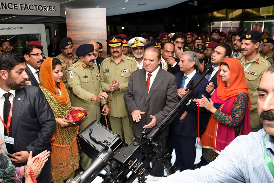
At IDEAS 2016, in Karachi, Pakistan, the Pakistani company Shibli is showcasing the Tarsier, one of the most advanced thermal weapon sights. The device is designed to enhance operational awareness through surveillance and target acquisition regardless of environmental constraints in both day & night scenarios.
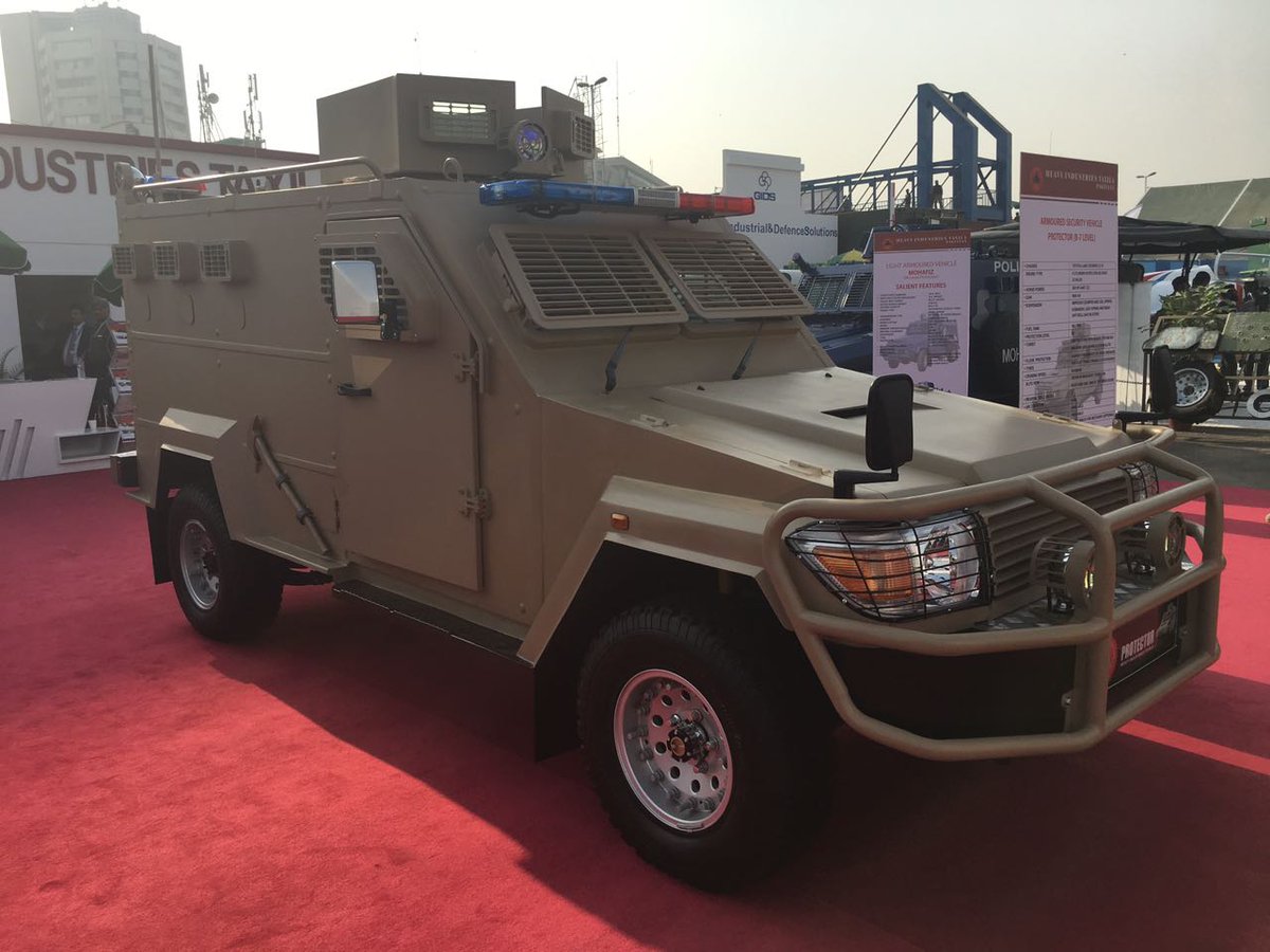
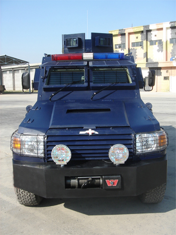
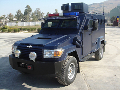
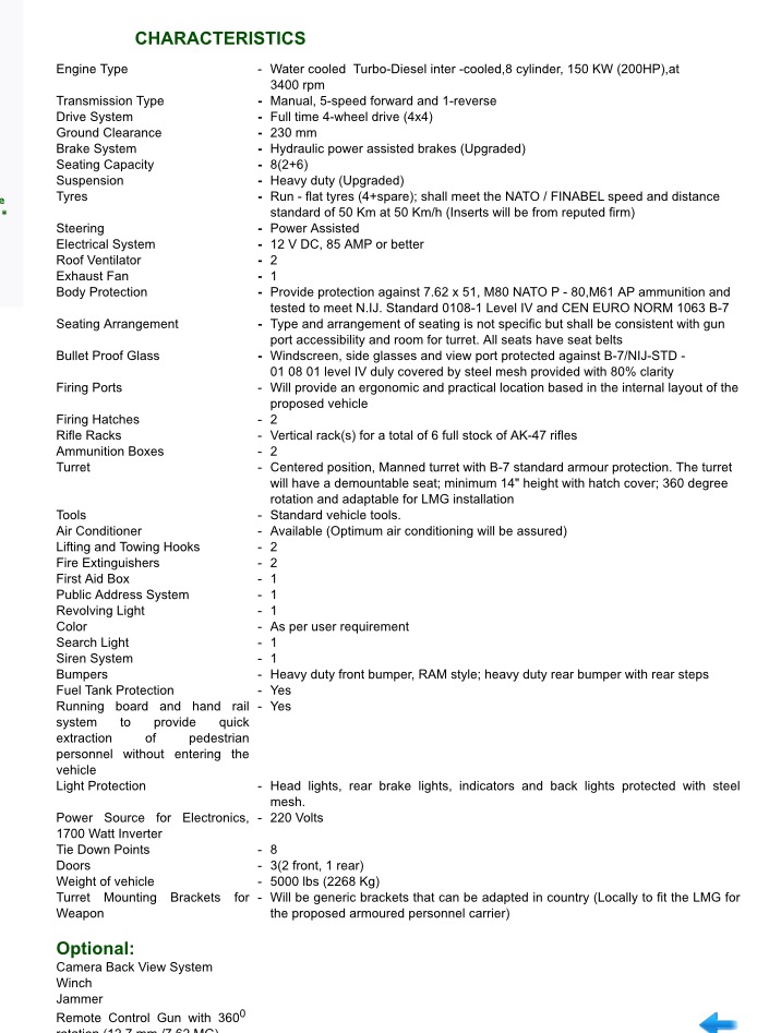
Protector
PK-16 HMG
Protector AV;
SKUA SR – THERMAL BINOCULAR
Thermal Binocular
Skua SR incorporates cutting-edge technologies into a lightweight and compact imaging system ideal for ground forces engaged in perimeter defence or tasked with holding ground.
The Skua uses an uncooled detector based IR core that is one of the most advanced in the world for a crisp and clear image. Featuring electronic zoom and up to 8 hours of operating time with a standard AA battery pack, the Skua can also be mounted on a Tripod in order to fulfill a variety of roles effectively.
. State-of-the-art uncooled 640 x 480 detector
. Lightweight and very compact
. Ruggedized and always ready to use
. Simple and ergonomic control
. Electronic zoom
. High resolution color OLED micro display
. Human recognition: 0.5 km
. Vehicle recognition: 1.0 km
. More than 8 hours operating time with one standard AA battery pack (4 batteries)
![[IMG] [IMG]](/vb/proxy.php?image=https%3A%2F%2Fdefence.pk%2Fattachments%2F11b-1-jpg.311347%2F&hash=42c44fcdf1eaef98a3389e24abf7e03c)
![[IMG] [IMG]](/vb/proxy.php?image=https%3A%2F%2Fdefence.pk%2Fattachments%2F5-1-jpg.311348%2F&hash=ef6add549f691483ea9034e1d5304a16)
![[IMG] [IMG]](/vb/proxy.php?image=https%3A%2F%2Fdefence.pk%2Fattachments%2Fskua-lr-jpg.311349%2F&hash=c9376598ffb231c85d3384d134310fe5)
![[IMG] [IMG]](/vb/proxy.php?image=https%3A%2F%2Fdefence.pk%2Fattachments%2Ftarsier-jpg.311350%2F&hash=0c69acd0066cb6758238d0e74ced4014)
Thermal Binocular
Skua SR incorporates cutting-edge technologies into a lightweight and compact imaging system ideal for ground forces engaged in perimeter defence or tasked with holding ground.
The Skua uses an uncooled detector based IR core that is one of the most advanced in the world for a crisp and clear image. Featuring electronic zoom and up to 8 hours of operating time with a standard AA battery pack, the Skua can also be mounted on a Tripod in order to fulfill a variety of roles effectively.
. State-of-the-art uncooled 640 x 480 detector
. Lightweight and very compact
. Ruggedized and always ready to use
. Simple and ergonomic control
. Electronic zoom
. High resolution color OLED micro display
. Human recognition: 0.5 km
. Vehicle recognition: 1.0 km
. More than 8 hours operating time with one standard AA battery pack (4 batteries)
POF stall in IDEAS

Short Range Ground Surveillance Radar
We are working on development of short range ground surveillance radar for detection of moving targets. The project provides an opportunity to develop know-how of complete electronic system design and development and at the same time, the project acts as a platform for working on research areas of current interest such as automatic target classification, high resolution representation of radar micro-Doppler signal and rain clutter mitigation (range enhancement using signal processing). Our electronic system development effort is geared towards acquiring the know-how to conceive design and develop a complete electronic system that meets a given set of user requirements. In order to meet these system level requirements we have designed and fabricated its components such as antenna, microwave circuits and modules, baseband circuits, DSP system, built-in test and monitoring, turn tilt platform and mechanical hardware.
NR-V3, a solid state coherent pulse doppler radar for detection of moving vehicles and pedestrians up to a range of 4 km for pedestrians and 12 km for vehicles
![[IMG] [IMG]](/vb/proxy.php?image=https%3A%2F%2Fdefence.pk%2Fattachments%2Fradar-jpg.91696%2F&hash=9c700c84c029317107ce80fb87188060)
Microstrip Antennas and Arrays
16x12 Folded Dipole Array Antenna:
Specifications:
Half power Beamwidth E plane : 4.2º H plane : 5.7º
Gain 28±1 dB
Sidelobe Level ≤ -18 dB
Frequency Ku Band
VSWR Bandwidth 800 MHz
![[IMG] [IMG]](/vb/proxy.php?image=https%3A%2F%2Fdefence.pk%2Fattachments%2Ffolded-dipole-16x12-jpg.91697%2F&hash=3059254ce5ca7569c6f46f03cba26cbe)
32x12 Folded Dipole Array Antenna:
Specifications:
Half power Beamwidth E plane : 2.2º H plane : 5.7º
Gain 29±1 dB
Sidelobe Level ≤ -20 dB
Frequency Ku Band
VSWR Bandwidth 600 MHz
![[IMG] [IMG]](/vb/proxy.php?image=https%3A%2F%2Fdefence.pk%2Fattachments%2Ffolded-dipole-32x12-jpg.91698%2F&hash=2461bf91798f4486fc373499a31da955)
8x8 Aperture Coupled Microstrip Patch Array Antenna:
Specifications:
Half power Beamwidth E plane : 9.9º H plane : 10.34º
Gain ??
Sidelobe Level ≤ -16 dB
Frequency ??
VSWR Bandwidth ??
![[IMG] [IMG]](/vb/proxy.php?image=https%3A%2F%2Fdefence.pk%2Fattachments%2Faperture8x8-jpg.91710%2F&hash=d21c4d1e8b83b1b096e58e822f590964)
Planer Inverted-F Antenna (PIFA):
In this work, multiband planer inverted-F antenna with 6mm height was designed, simulated in HFSS and fabricated for operating in the GSM, DCS and WLAN bands. In addition, a reduced height planer inverted-F antenna with 2mm height was also designed simulated and fabricated for application in multiband slim handsets.
Publications:
This work includes simulation and experimental results for wide band U-shaped side slots loaded linearly polarized rectangular microstrip antenna with broad side radiation characteristics suitable for onboard applications in S-band. Impedence bandwidth of 34.8% as compared to 2-5% bandwidth of conventional microstrip antenna has been achieved.
Publications:
In this work, frequency selective surface has been implemented over radome to address the issue of composite radome matching. Different planer artificial structures are implemented surrounding the antenna aperture to restore the broad coverage of patch antenna with low return loss. Implementation of artificially hard boundary in the form of longitudinal metallic strips restores the -3 dB beamwidth (
![[IMG] [IMG]](/vb/proxy.php?image=http%3A%2F%2Flatex.codecogs.com%2Fgif.latex%3F%5Ccong102%5E%7Bo%7D&hash=9ad0c0265da04bd9565a02e5e3261c88) ) of the antenna in E-plane at the cost of antenna gain. Soft ring over dielectric coating surrounding the antenna aperture is optimized here for broad beamwidth (
) of the antenna in E-plane at the cost of antenna gain. Soft ring over dielectric coating surrounding the antenna aperture is optimized here for broad beamwidth (
![[IMG] [IMG]](/vb/proxy.php?image=http%3A%2F%2Flatex.codecogs.com%2Fgif.latex%3F%5Ccong100%5E%7Bo%7D&hash=95659f905efc2fbf196dafa2d9090151) ) in E-plane with increased gain near to 7 dB by suppressing the creeped RF energy from thick dielectric coating.
) in E-plane with increased gain near to 7 dB by suppressing the creeped RF energy from thick dielectric coating.
Publications:
Microstrip Star Shaped Patch Antenna:
Specifications:
Half power Beamwidth E plane : 34º H plane : 36º
![[IMG] [IMG]](/vb/proxy.php?image=https%3A%2F%2Fdefence.pk%2Fattachments%2Fqasim-starshaped-png.91711%2F&hash=a5593605dbd1d4848df3cdaac5dea58d)
Gain 10.2 dBi
Frequency Ku Band
Fractal Antennas
High Directivity Fractal Antenna:
Specifications:
Half power Beamwidth E plane : 27º H plane : 31º
Gain 12.5 ± 0.5 dB
Sidelobe Level ≤ -12.5 dB
Frequency 3 GHz
VSWR Bandwidth 450 MHz
![[IMG] [IMG]](/vb/proxy.php?image=https%3A%2F%2Fdefence.pk%2Fattachments%2F85996b5ef30e501601f46df8c910be00-png.91721%2F&hash=943667a2420d1105b52504d86565b0e3)
Publications:
Multiband Fractal Antenna:
Sierpinski fractal monopole antenna and its scale factor variations have been studied. The Sierpinski fractal monopole antenna designed exhibits multiband behavior with three log-periodic bands, spaced with a log-period of 2. The number of log-periodic bands is proportional to the number of fractal iterations. By changing the geometrical scale factor of the Sierpinski Fractal, the band positions are changed accordingly, which confirms that the band positions correspond to the geometrical scale factor of the Sierpinski fractal, but it results in poor input matching (the return loss of the three log periodic bands being approximately -9 dB). This poor input matching is improved by using microstrip line feeding and consequently the return loss of the log-periodic bands improves to less than -15 dB.
![[IMG] [IMG]](/vb/proxy.php?image=https%3A%2F%2Fdefence.pk%2Fattachments%2F43fc8ad1d2441658e1b48f97aed8f230-png.91722%2F&hash=bfd149122725a84b5b92306ac4403246)
![[IMG] [IMG]](/vb/proxy.php?image=https%3A%2F%2Fdefence.pk%2Fattachments%2Fc4cc452f19ed26bb1e0bf4c22bfb22b3-png.91723%2F&hash=8f76c3edf2c3351c442266ee34038d74)
Publications:
We are working on development of short range ground surveillance radar for detection of moving targets. The project provides an opportunity to develop know-how of complete electronic system design and development and at the same time, the project acts as a platform for working on research areas of current interest such as automatic target classification, high resolution representation of radar micro-Doppler signal and rain clutter mitigation (range enhancement using signal processing). Our electronic system development effort is geared towards acquiring the know-how to conceive design and develop a complete electronic system that meets a given set of user requirements. In order to meet these system level requirements we have designed and fabricated its components such as antenna, microwave circuits and modules, baseband circuits, DSP system, built-in test and monitoring, turn tilt platform and mechanical hardware.
NR-V3, a solid state coherent pulse doppler radar for detection of moving vehicles and pedestrians up to a range of 4 km for pedestrians and 12 km for vehicles
Microstrip Antennas and Arrays
16x12 Folded Dipole Array Antenna:
Specifications:
Half power Beamwidth E plane : 4.2º H plane : 5.7º
Gain 28±1 dB
Sidelobe Level ≤ -18 dB
Frequency Ku Band
VSWR Bandwidth 800 MHz
32x12 Folded Dipole Array Antenna:
Specifications:
Half power Beamwidth E plane : 2.2º H plane : 5.7º
Gain 29±1 dB
Sidelobe Level ≤ -20 dB
Frequency Ku Band
VSWR Bandwidth 600 MHz
8x8 Aperture Coupled Microstrip Patch Array Antenna:
Specifications:
Half power Beamwidth E plane : 9.9º H plane : 10.34º
Gain ??
Sidelobe Level ≤ -16 dB
Frequency ??
VSWR Bandwidth ??
Planer Inverted-F Antenna (PIFA):
In this work, multiband planer inverted-F antenna with 6mm height was designed, simulated in HFSS and fabricated for operating in the GSM, DCS and WLAN bands. In addition, a reduced height planer inverted-F antenna with 2mm height was also designed simulated and fabricated for application in multiband slim handsets.
Publications:
- Rehman Ahmed, “Low Profile Antennas for Mobile Communication Applications,” MS Thesis, College of E&ME, NUST, 2009.
This work includes simulation and experimental results for wide band U-shaped side slots loaded linearly polarized rectangular microstrip antenna with broad side radiation characteristics suitable for onboard applications in S-band. Impedence bandwidth of 34.8% as compared to 2-5% bandwidth of conventional microstrip antenna has been achieved.
Publications:
- Hafiz Muhammad Jafar, “Development of Compact Wide-band Broad Side RMSA Suitable for on-board Applications,” MS Thesis, College of E&ME, NUST, 2009.
In this work, frequency selective surface has been implemented over radome to address the issue of composite radome matching. Different planer artificial structures are implemented surrounding the antenna aperture to restore the broad coverage of patch antenna with low return loss. Implementation of artificially hard boundary in the form of longitudinal metallic strips restores the -3 dB beamwidth (
Publications:
- Javed Ahmad, “Ratiation Pattern Improvement of Patch Antenna Embedded in Dielectric Coating using Artificial Surfaces,” MS Thesis, College of E&ME, NUST, 2009.
Microstrip Star Shaped Patch Antenna:
Specifications:
Half power Beamwidth E plane : 34º H plane : 36º
Gain 10.2 dBi
Frequency Ku Band
Fractal Antennas
High Directivity Fractal Antenna:
Specifications:
Half power Beamwidth E plane : 27º H plane : 31º
Gain 12.5 ± 0.5 dB
Sidelobe Level ≤ -12.5 dB
Frequency 3 GHz
VSWR Bandwidth 450 MHz
Publications:
- Abbas Bin Younas Awan, Zubair Ahmed and Mojeeb Bin Ihsan, “A New High Directivity Fractal Antenna Based on the Modified Koch Snowflake Geometry” Asia Pacific Microwave Conference (APMC 2010) Dec 7-10, 2010, Yokohama Japan.
- Abbas Bin Younas Awan, “High Directivity Fractal Antenna,” MS Thesis, College of E&ME, NUST, 2010.
Multiband Fractal Antenna:
Sierpinski fractal monopole antenna and its scale factor variations have been studied. The Sierpinski fractal monopole antenna designed exhibits multiband behavior with three log-periodic bands, spaced with a log-period of 2. The number of log-periodic bands is proportional to the number of fractal iterations. By changing the geometrical scale factor of the Sierpinski Fractal, the band positions are changed accordingly, which confirms that the band positions correspond to the geometrical scale factor of the Sierpinski fractal, but it results in poor input matching (the return loss of the three log periodic bands being approximately -9 dB). This poor input matching is improved by using microstrip line feeding and consequently the return loss of the log-periodic bands improves to less than -15 dB.
Publications:
- Muhammad Waqas, Zubair Ahmed and Mojeeb Bin Ihsan, “Multiband Sierpinski Fractal Antenna”, IEEE International Multitopic Conference, Islamabad, Pakistan, Dec 2009, pp. 376-381.
- Muhammad Waqas, “Multiband Fractal Antenna,”, MS Thesis, College of E&ME, NUST, 2009.
Triangular Patch Antenna Using Partial Koch Fractal Boundary:
Specifications:
Half power Beamwidth E plane : 70º H plane : 112º
Gain 9.5±0.5 dB
Sidelobe Level ≤ -18 dB
Frequency 3.6 GHz
VSWR Bandwidth 240 MHz
![[IMG] [IMG]](/vb/proxy.php?image=https%3A%2F%2Fdefence.pk%2Fattachments%2F3dfe053e5c4c0a09ec3aa8a07fc7a476-png.91724%2F&hash=4c0f57911ff8e0e5cce7f5f9d234dc82)
Publications:
Slotted Waveguide Antennas
20x12 Slotted Wave Guide Array Antenna:
Specifications:
Half power Beamwidth E plane : 4.1º H plane : 7.2º
Gain 28.5 ± 0.5 dB
Sidelobe Level ≤ -19 dB
Frequency Ku Band
VSWR Bandwidth 100 MHz
![[IMG] [IMG]](/vb/proxy.php?image=https%3A%2F%2Fdefence.pk%2Fattachments%2Fa108142a5355a8fdc3dd8e9dc992577f-png.91728%2F&hash=d33b0e8bddfc2c28b8ffea5a19c5f916)
Publications:
Reflector and Reflect Array Antennas
Ku Band Reflect Array Antenna:
Specifications:
Half power Beamwidth E plane : 4º H plane : 5º
Gain 22.2 dB
Sidelobe Level ≤ -10 dB
Frequency Ku Band
![[IMG] [IMG]](/vb/proxy.php?image=https%3A%2F%2Fdefence.pk%2Fattachments%2F76f33b79f7985ed83a96f7d4a58c8986-png.91729%2F&hash=814fb67ba8d7a987fa3cfab746cc4f95)
Journal Publications:
Frequency Independent Antennas
Spiral Antenna:
Archimedean Spiral and Equiangular Spiral Antenna has been designed, simulated and fabricated for the 2GHz to 18GHz bandwidth, |Axial ratio| ≤ 3dB and typical VSWR ≤ 2.
15% Reduction in size has been achieved and the parameters of Meander Arm Spiral are better than the classical antenna.
![[IMG] [IMG]](/vb/proxy.php?image=https%3A%2F%2Fdefence.pk%2Fattachments%2Ffa1c90d1090f9ad8d1f3b8eadfe40251-png.91730%2F&hash=a15fddebe5a624d474f2d5c70cf10a85)
Publications:
Automatic Target Classification
We are working on automatic target recognition problem for ground surveillance radar NR-V3. The goal of this research is to develop an automatic target classifier that can classify ground targets detected by NR-V3 radar. The work is based on extracting the micro-Doppler features from the backscattered signal using signal processing and then classifying them using machine learning techniques.
In addition, we are developing high resolution 2D time-frequency representation of pedestrian micro-Doppler signature.
![[IMG] [IMG]](/vb/proxy.php?image=https%3A%2F%2Fdefence.pk%2Fattachments%2Fb3e1bcf8e6c7559de8a4ce7179ebb009-png.91732%2F&hash=bdde89dfedd491ab4cbcd0689d0668e6)
Scatter plot showing first 3 feature vectors of NR-V3 data
This work has resulted in a number of publications :
Machine Learning:
Joint time-frequency Representation:
![[IMG] [IMG]](/vb/proxy.php?image=https%3A%2F%2Fdefence.pk%2Fattachments%2F5b0db577983c8d06897a3a74b89362d9-png.91733%2F&hash=1025924ce8b04c4a951a0c5efcf9f12b)
Microwave Systems
Microwave Transmitter Module for Ku Band
![[IMG] [IMG]](/vb/proxy.php?image=https%3A%2F%2Fdefence.pk%2Fattachments%2F826ca8c887044c2e0f91a91f74ba5195-jpg.91734%2F&hash=5b10e049052611e1f415beaf514fe674)
Microwave Transmitter Module for Ku Band
Microwave Tranceiver Module for Ku Band
![[IMG] [IMG]](/vb/proxy.php?image=https%3A%2F%2Fdefence.pk%2Fattachments%2F08f6b1589e61ff174b285fd0451aee51-jpg.91735%2F&hash=012f236a5bb73740a9288ecbe45186b4)
Microwave Tranceiver Module for Ku Band
Microwave Receiver Module for Ku Band
![[IMG] [IMG]](/vb/proxy.php?image=https%3A%2F%2Fdefence.pk%2Fattachments%2Ff4d09dac64f750788ef1f1099ceaab1c-jpg.91736%2F&hash=f794e458b4335f089e3af55c91dbb07d)
Microwave Receiver Module for Ku Band
Amplifiers
Spatial Power Combining in Rectangular Waveguides using Dense Finline Arrays:
Spatial power combiners using dense finline arrays (tapered slot antennas) arranged in tray configuration and enclosed in a standard Ku band waveguide (WR-62) have been designed in this work. The design of the finline taper is the most challenging aspect in this work. Before the tapers can be synthesized, a relationship between phase constant of the finline array and its geometrical parameters must be established which can only be achieved through full wave EM analysis. Matlab codes were developed using Spectral Domain Method (SDM) to extract this relationship for single-tray finline, two-tray finline and four-tray finline configuration. Results of SDM codes were also compared with Ansoft HFSS and were found to be in good aggrement. Two tray finline and Four tray finline tapers along with dielectric matching, connected back to back were fabricated and tested using Time Domain Gating feature of Network Analyzer. Results indicate measured return loss of 26.3 dB as compared to simulated return loss of 23.5 dB for single tray finline, 19 dB as compared to simulated return loss of 18.6 dB for two tray finline and 16 dB as compared to simulated return loss of 15.5 dB for four tray finline at 16 GHz.
Publications:
Specifications:
Half power Beamwidth E plane : 70º H plane : 112º
Gain 9.5±0.5 dB
Sidelobe Level ≤ -18 dB
Frequency 3.6 GHz
VSWR Bandwidth 240 MHz
Publications:
- D. Fazal, Q.U. Khan and Mojeeb Bin Ihsan “Use of partial Koch boundaries for improved return loss, gain and sidelobe levels of triangular patch antenna” Electronic Letters 19th July 2012 Vol.48 No.15.
- D. Fazal, “Improvement in the Performance of Triangular Patch Antenna using Partial Koch Fractal Boundary,”, MS Thesis, College of E&ME, NUST, 2012.
Slotted Waveguide Antennas
20x12 Slotted Wave Guide Array Antenna:
Specifications:
Half power Beamwidth E plane : 4.1º H plane : 7.2º
Gain 28.5 ± 0.5 dB
Sidelobe Level ≤ -19 dB
Frequency Ku Band
VSWR Bandwidth 100 MHz
Publications:
- Sara H. Dar, Zubair Ahmed, Mojeeb Bin Ihsan, “Characterization of Waveguide Slots Using Full Wave EM Analysis Software HFSS’, IEEE INMIC Conference Proceedings, Karachi, Pakistan, Dec 2008, pp. 85-90.
- Sara Hameed Dar, Zubair Ahmed, and Mojeeb Bin Ihsan “Design of a Low Side Lobe Slotted Waveguide Planar Array”, Fifth International Bhurban Conference on Applied Sciences and Technology, IBCAST, Islamabad, Pakistan, 8th -11th January, 2007. pp. 31-34.
- Sara H. Dar, “Design of a Low Side Lobe Slotted Waveguide Planar Array,” College of E&ME, NUST, 2007.
Reflector and Reflect Array Antennas
Ku Band Reflect Array Antenna:
Specifications:
Half power Beamwidth E plane : 4º H plane : 5º
Gain 22.2 dB
Sidelobe Level ≤ -10 dB
Frequency Ku Band
Journal Publications:
- Muhammad Wasif, Zubair Ahmed and Mojeeb Bin Ihsan, “Performance of Thinned Mcrostrip Reflectarrays” IACSIT International Journal of Engineering and Technology, Vol-2, No. 2, pp 581-585 Dec 2010.
- Muhammad Wasif, Zubair Ahmed and Mojeeb Bin Ihsan, “Performance Comparison of Different Aperture Shapes for Microstrip Reflectarray,” German Microwave Conference (GeMIC), Germany, Mar 2010, pp 250 to 253.
- Muhammad Wasif, Zubair Ahmed and Mojeeb Bin Ihsan, “Comparison of Microstrip Reflectarray for Different Aperture Shapes and Different Grid Settings of Elementary Antennas on its Aperture” IEEE International Conference on Antennas, Propagation and Systems (INAS 2009), Dec 2009, Johor Malaysia. Pp.110-1 to 110-5.
- Muhammad Wasif, “Design and Fabrication of Microstrip Reflectarray using Patches of Variable Size,” College of E&ME, NUST, 2009.
Frequency Independent Antennas
Spiral Antenna:
Archimedean Spiral and Equiangular Spiral Antenna has been designed, simulated and fabricated for the 2GHz to 18GHz bandwidth, |Axial ratio| ≤ 3dB and typical VSWR ≤ 2.
15% Reduction in size has been achieved and the parameters of Meander Arm Spiral are better than the classical antenna.
Publications:
- Zia Ullah Khan, “Simulation Design of Spiral Antenna,” MS Thesis, College of E&ME, NUST, 2009
Automatic Target Classification
We are working on automatic target recognition problem for ground surveillance radar NR-V3. The goal of this research is to develop an automatic target classifier that can classify ground targets detected by NR-V3 radar. The work is based on extracting the micro-Doppler features from the backscattered signal using signal processing and then classifying them using machine learning techniques.
In addition, we are developing high resolution 2D time-frequency representation of pedestrian micro-Doppler signature.
Scatter plot showing first 3 feature vectors of NR-V3 data
This work has resulted in a number of publications :
Machine Learning:
- A. Javed, S. Liaqat, M. B. Ihsan, "Support vector machine based micro-Doppler signature classification of ground targets", Radar Conference (EuRAD), 2013, 10th European, Oct. 9 2013 – Oct. 11 2013, pp. 168-171.
- A. Javed, A. Ejaz, S. Liaqat, A. Ashraf, M. B. Ihsan, "Automatic target classifier for a ground surveillance radar using linear discriminant analysis and logistic regression", in Radar Conference (EuRAD), 2012 9th European, Oct 31 2012-Nov 2, 2012, pp 302-305.
- S. Liaqat, S. A. Khan, A. I. Bhatti, M. B. Ihsan, S. Z. Asghar, A, Ejaz, "Automatic recognition of ground radar targets based on target RCS and short time spectrum variance", in Innovations in Intelligent Systems and Applications 2011 (INISTA 2011), International Symposium on, pp 164-167, Jun 2011.
Joint time-frequency Representation:
- S. Liaqat , M. B. Ihsan, S. Z. Asghar , A. Ejaz, A. Javed, "High resolution 2D time frequency representation of radar micro-Doppler pedestrian signal", Radar Conference (EuRAD), 2013, 10th European, Oct. 9 2013-Oct. 11 2013, pp 515-518.
Microwave Systems
Microwave Transmitter Module for Ku Band
Microwave Transmitter Module for Ku Band
Microwave Tranceiver Module for Ku Band
Microwave Tranceiver Module for Ku Band
Microwave Receiver Module for Ku Band
Microwave Receiver Module for Ku Band
Amplifiers
Spatial Power Combining in Rectangular Waveguides using Dense Finline Arrays:
Spatial power combiners using dense finline arrays (tapered slot antennas) arranged in tray configuration and enclosed in a standard Ku band waveguide (WR-62) have been designed in this work. The design of the finline taper is the most challenging aspect in this work. Before the tapers can be synthesized, a relationship between phase constant of the finline array and its geometrical parameters must be established which can only be achieved through full wave EM analysis. Matlab codes were developed using Spectral Domain Method (SDM) to extract this relationship for single-tray finline, two-tray finline and four-tray finline configuration. Results of SDM codes were also compared with Ansoft HFSS and were found to be in good aggrement. Two tray finline and Four tray finline tapers along with dielectric matching, connected back to back were fabricated and tested using Time Domain Gating feature of Network Analyzer. Results indicate measured return loss of 26.3 dB as compared to simulated return loss of 23.5 dB for single tray finline, 19 dB as compared to simulated return loss of 18.6 dB for two tray finline and 16 dB as compared to simulated return loss of 15.5 dB for four tray finline at 16 GHz.
Publications:
- M. Anis Chaudhary, “Spatial Power Combining in Rectangular Waveguides using Dense Finline Arrays,” MS Thesis, College of E&ME, NUST, 2010.
a flayer of POF for common public

a newspaper ad of HIT pakistan

Grifo Radar
Grifo radar is multi-mode pulse Doppler all weather fire control radar. PAC has the capability of not only producing the airborne fire control radars but also has vast experience in maintaining three variants of Grifo radars. PAC has produced a number of Grifo radar systems for PAF Fleet in collaboration with M/S Selex Electronic Systems Italy. Grifo family of radars is digital fire control system designed to improve air to air and air to ground performance. Radars are capable of detecting and tracking the targets at all altitudes and all aspects. Radars have powerful and accurate Built-In Test (BIT) system followed by auto calibration for the ease of smooth operation and better maintenance.
Radar Warning Receiver (RWR)
Radar Warning Receiver (RWR) is being co-produced in collaboration with M/s CEIEC China and is designed to provide the pilot with real time and unambiguous threat warning over 360 degrees thus reducing vulnerability of the combat aircraft to radar associated weapons. Currently two different models of RWR are available i.e. BM/KJ-8602 RWR and BM/KJ-8602A RWR. PAC also provides the life cycle maintenance of these two RWR models to PAF.
Global Attitude Heading reference System (GAHRS)
Global Attitude Heading Reference System (GAHRS) is an avionics subsystem of JF-17 aircraft which provides high performance measurement of aircraft attitude by using highly reliable optical fiber gyroscopes and accelerometers. GAHRS is a backup system of Inertial Navigation System (INS). In case of INS failure, it provides roll, pitch and heading information to Weapon Mission Management Computer (WMMC) using RS 422 interface.
Identification of Friend or Foe (IFF)
Identification of Friend or Foe (IFF) system is solid state, airborne and selective transponder being co-produced in collaboration with M/s JIUZHOU China. It is used for identification of friend or foe. The system is compatible which civil ATC radar beacon system for air traffic control. PAC also provides the life cycle maintenance support to the JZ/YD 125 IFF system.
Integrated Survivable Recorder (ISR)
Integrated Survivable Recorder (ISR) is an important LRU of aircraft Electro Mechanical Management System (EMMS). It receives flight and audio data being sent from electromechanical management computer through HDLC bus and records them in crash survival memory unit (CSMU). After recording the data in accordance with the bus commands, it downloads the recorded data and sends it to electromechanical management computer.
Light Warning System (LWS)
Light warning system is used to display emergency warning signals. It's main purpose is to draw the pilot's attention to the warning signals for a proper timely action. It has a Built in Test Function for checking its serviceability and provides four warning levels according to degree of emergency related to flight safety and mission plan.
Stores Management System (SMS)
SMS is able to manage and control guns, bombs, external tank and stores such as armament at stations and pods which comply with MIL-STD-1760C-97. It also ensures that stores functions are carried out in addition to offering certain safety measures.
Smart Head Up Display (SHUD)
SHUD is an integrated electro optical display unit, and is one of the important units of aircraft. It is the main window which provides flight and combat information to the pilot. It employs command control mode to generate flight symbology required in navigation and combat. The displayed symbology are imaged to infinity and superimposed with outside scene, enabling the pilot to view the displayed information without adjusting eyes while observing the outside scene. The unit is NVIS compatible. It outputs superimposed video signals for recording, so as to provide evidences for combat and training analysis.
Instrument Landing System (ILS)
ILS is used for aircraft approach and landing. It receives and processes the signals transmitted from ground localizer and glide-slope stations. It provides pilot deviation information from the given course and glide path so as to lead aircraft to the visual runway entrance according to the correct path track. The equipment is one of the essential systems which ensures safe landing of the aircraft under adverse weather conditions.
Back Up Acquisition Computer (BAC)
BAC is a back up computer for avionics systems and provides flight critical information to the pilot in case of main bus / mission management computer failure. BAC accepts data from flight critical systems on a separate RS 422 data line and communicates the same to Multi Function Displays. It also provides excitation voltage to hydraulic and brake sensors.
Inertial Navigation System (INS)
Radar Altimeter provides data on 1553 Bus pertaining to aircraft actual height above ground level. This data can be displayed on Head Up Display (HUD).
Smart Multi Function Colour Display (SMFCD)
SMFCD is a NVIS compatible display providing the graphical interface of the avionics & non-avionics systems to the pilot. Input to SMFCDs are 1553B data bus, RS-422 XGA In/out and RGB Video Out.
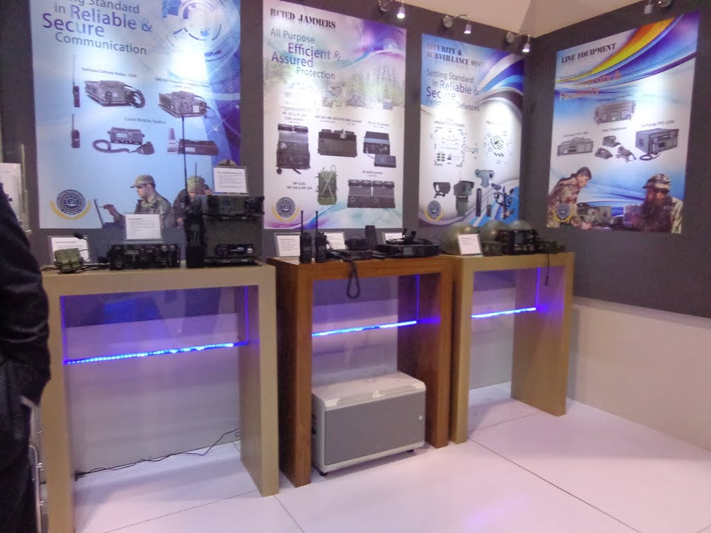
Communication Systems

المواضيع المشابهة
- الردود
- 8
- المشاهدات
- 1K
- الردود
- 142
- المشاهدات
- 19K
- الردود
- 91
- المشاهدات
- 13K

